Create and Deploy ML Model using Low Power Microcontroller and TinyML

Image Source:
Zaiets Roman/Stock.adobe.com
By Adam Taylor for Mouser Electronics
Published August 2, 2022
Bill of Materials:
- Analog Devices MAX32650FTHR Eval Kit
- Active Load – capable of constant current load
- Power Supply – with a current limit
Introduction
Many systems include a built-in test (BIT) which monitors the behaviour of the system to detect any failures.
Many BIT Systems however indicated a simple pass / fail structure, where a failure means the equipment must be
powered down and stop operation. This equipment being monitored could range from industrial plant to satellites
or aircraft systems. Unexpected failures of these system can have significant impacts, a better system is one of
prognostics where data is analysed to indicate the system is beginning to fail. Often this prognostic is looking
at the sensor data and extracting information before it becomes obvious that there is an issue.
This is where TinyML comes into play. Using low power processors, typically those which are also used for other
system features such as BIT, a machine learning model can be deployed which is able to detect changes in sensor
data and indicate the need to perform scheduled maintenance at an appropriate time.
In this project we are going to show how to create a TinyML model using edge impulse to monitor current / voltage
changes in a system power rail. To do this we will be using an active current load which is able to draw
different current levels from a power supply. The voltage output by the supply will experience slight changes
depending upon the current drawn. We may also be able to define the failure case for some failure modes.
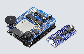
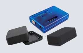
For this project we will be using the MAX32650FTHR evaluation board (Figure 1), this provides the
developer with an Arm M4 processor with Floating Point Unit, running at 120MHz. Memory wise the board provides
3MB of flash and 1MB of SRAM.
Connectivity is provided by several IO which are connected to IO on the processor these can be used as either
GPIO or an alternate function such as SPI, I2C etc. As the MAX32650FTHR complies with the Adafruit feather
format it also provides six ADC inputs (Figure 2) which can quantise values between 0 and 3v,
this is provided by an external ADC the MAX11261. It is this ADC which we are going to use to sample the data.
Figure 1: MAX32650FTHR IO (Source: MAX32650FTHR Evaluation
Kit-Evaluates: MAX32650 (mouser.com))
Figure 2: MAX32650FTHR ADC (Source: MAX32650FTHR Evaluation
Kit-Evaluates: MAX32650 (mouser.com))
First, however, we need to set up the development environment for the MAX32650FTHR.
Setting up the development environment
Here’s what we get in the box when we order the evaluation board:
- MAX32650FTHR Eval Board
- MAX32625PICO
- Serial Wire Debug (SWD) Cable
- Two USB A to Micro B cables
The MAX32625 PICO acts as the SW/JTAG programmer / debugger for the MAX32650FTHR, to do this the MAX32625PICO
comes loaded with a DAPLink image. One rather nice touch is the
MAX32625PICO comes in a compact tin along with the SWD Cable (Figure 3). The MAX32625PICO is
actually an interesting development board in its own right.
Figure 3: MAX32650FTHR Tin (Source: Adam Taylor)
To get started we need to install
the Maxim design tools on our development machine, we can install them on Windows, MAC, or Linux development
systems. Like many SW development environments, it is based around Eclipse.
Installation is straightforward, each of the steps for installation can be viewed in the images below
(Figure 4 – 13).
Figure 4: Download the appropriate development environment (Source: Adam
Taylor)
Figure 5: Download the SDK for the MAX32650 (Source: Adam Taylor)
Figure 6: Sign in or create an account to complete the download (Source:
Adam Taylor)
Figure 7: Run the downloaded executable (Source: Adam Taylor)
Figure 8: Select the installation directory when prompted (Source: Adam
Taylor)
Figure 9: Leave the installation defaults unchanged (Source: Adam
Taylor)
Figure 10: Accept the license agreement (Source: Adam Taylor)
Figure 11: Add the menu shortcut (Source: Adam Taylor)
Figure 12: Install the development environment (Source: Adam Taylor)
Figure 13: Installation Complete (Source: Adam Taylor)
Once the tool is installed, we are ready to begin creating an example application. To do this, first, we need to
open the Maxim SDK and Select the workspace (Figure 14).
Figure 14: Open a new workspace (Source: Adam Taylor)
With the workspace selected the next step is to create a new application, once MaximSDK loads, close the welcome
page, and select Maxim Microcontrollers under the project explorer window (Figure 15).
Figure 15: Open a new workspace (Source: Adam Taylor)
This will open a new wizard to create the application, enter a project name in this case we are calling it
hello_world (Figure 16).
Figure 16: Create a hello world project (Source: Adam Taylor)
With the project name defined click next, this will allow us to select the processor type, board type, select the
example application and the debugger - in this case the MAX32625PICO.
This will create the basic hello world application, now we are ready to connect the hardware to debug the
application.
The first thing we need to do is remove the cover on the MAX32650FTHR boards SWD/DAP connection (Figure
17).
Figure 17: MAX32650FTHR (Source: Adam Taylor)
We then need to connect the MAX32625PICO with the MAX32650FTHR board, to do this we use the SWD cable. The
MAX32650FTHR board connector is keyed and the cable only fits one direction. However, the MAX32625PICO is not
keyed and as such we need to ensure it aligns correctly. The red strip should align as shown below
(Figure 18).
Figure 18: Connecting the SW/JTAG programmer (Source: Adam Taylor)
With the two MAX boards connected (Figure 19) and connected over USB to the development machine
we can debug our application using MaximSDK.
Figure 19: Programmer and Dev board connected (Source: Adam Taylor)
We can select the RUN/Debug elements as desired from the drop-down menu in the tool bar, double check we have
built the application (Figure 20). If not hit the hammer on the tool bar to build the binary
and download the application to the MAX32650FTHR.
Figure 20: Hello World example (Source: Adam Taylor)
If you select Debug the application will halt paused ready for single stepping for running (Figure
21).
Figure 21: Debugging the Hello World Application (Source: Adam Taylor)
When the application downloads and halts awaiting execution, we can open a serial terminal program select a baud
rate of 115200, no parity and one stop bit. Running the application, you should then see output in the terminal
like below (Figure 22).
Figure 22: Hello World Application (Source: Adam Taylor)
Now we have a development environment we can use with the MAX32650FTHR and we can start on the development of the
application.
Creating the Application
The first element of the design is to update the design to be able to work with I2C and to configure the ADC to
read samples.
To input data into Edge Impulse we will be using the serial port to output data formatted in a CSV file. This will
allow the terminal program which logs the serial data to save the data directly in the right format.
To enable the ADC, we need to do the following.
- Configure GPIO Bank 0 pin 16 to be an output and drive it high – this drives the reset for the ADC,
when low the ADC is in reset
- Configure the I2C controller one to be a master, with the targe slave address to be 0x30
- Configure the ADC to sample on channel one, unipolar and continuous
- Read back the values from the FIFO, we do this on a one second sampling rate, reading the sensor when the
FIFO has samples.
- Output each sample over the serial port for logging.
The name of the log file captured over the serial link is the label when we upload it (Figure
23).
Figure 23: Setting up logging (Source: Adam Taylor)
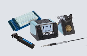
Now we need to set up the test equipment to create the operational and fault state data we require for the
experiment.
To do this I arranged the equipment in the following manner, a power supply set to output 1.5v (a common core
voltage) with a current limit of 500mA. The output of this power supply was connected to an active load, this
active load can be used to vary the current drawn from the power supply. The ADC input would be connected to the
terminals of the active load (Figure 24).
Figure 24: Hardware connections (Source: Adam Taylor)
The active load was configured to give out several currents which would represent operational and fault
conditions.
Running the applications with different several times, we captured several files to be uploaded into edge impulse
(Figure 25).
Figure 25: Training Files (Source: Adam Taylor)
To get started within Edge Impulse we first need to sign up for an account (Figure 26), accounts are free.
Figure 26: Training Files (Source: Adam Taylor)
Once the account has been created, sign in and create a new project, I used the name MAX32650FTHR (Figure
27).
Figure 27: Creating the Project (Source: Adam Taylor)
Once the name has been entered, we will see a dashboard which prompts us to select the necessary data
(Figure 28).
Figure 28: Initial Project creation page (Source: Adam Taylor)
For this project we are not going to connect a board, but upload the CSV files, close the dialog and select data
acquisition (Figure 29).
Figure 29: Uploading Data (Source: Adam Taylor)
Select the upload data option and upload all the CSV files allowing Edge Impulse to perform the training/test
split (Figure 30).
Figure 30: Selecting the CSV files (Source: Adam Taylor)
Once these are uploaded, we can begin to create the impulse, generate the features, and train the network.
(Figure 31).
Figure 31: Creating the impulse (Source: Adam Taylor)
Once these have been created the next step is to generate the features (Figure 32).
Figure 32: Raw Data (Source: Adam Taylor)
With the features generated we can train the Neural Network (Figure 33 – 34).
Figure 33: NN Settings (Source: Adam Taylor)
Figure 34: NN Results (Source: Adam Taylor)
The final stage of model deployment is to test it against the test data, this is data which the model has not yet
seen to check its classification.
To do this we select the live test and select the test data sets to determine the performance pf the model.
Getting the model just right took us a few attempts and gathering of data was significant. Once we are happy with
the model, we can generate a C++ deployable library we can implement on the Maxim board (Figure
35).
Figure 35: Creating the deployment model (Source: Adam Taylor)
Figure 36: Deployment (Source: Adam Taylor)
Once this has been downloaded (Figure 36), we are able to unzip the application software
downloaded and create a new project for the MAX32650 board in MaximSDK (Figure 37).
Figure 37: Creating the EI project (Source: Adam Taylor)
With the project created select import and import the selected files from the deployment download (Figure
38).
Figure 38: Adding in the downloaded SDK (Source: Adam Taylor)
For the main.c file copy the procedures outlined at here in the Edge
Impulse documentation.
Into this data we can copy and paste the raw features data from the live classification page (Figure
39).
Figure 39: Extracting samples (Source: Adam Taylor)
This can be copied and pasted into the Edge Impulse code (Figure 40).
Figure 40: Running the application (Source: Adam Taylor)
We also need to make changes to the linker script which is provided under the MaximSDK installation path for the
board in question (Figure 41).
It can be found at the path <install>\MaximSDK\Libraries\CMSIS\Device\Maxim\MAX32650\Source\GCC
Figure 41: Linker Scripts (Source: Adam Taylor)
Once this complies, we can run it on the MAX32650FTHR and see the classified outcome as we do in Edge Impulse
Cloud.
Wrap Up
Now we have gathered the data samples, trained the network, and verified the networks performance on the
MAX32650FTHR. We can now include the same functionality in the end application which is deployed along with the
rest of the application also running on the MAX32650FTHR ensuring out system is protected by prognostics.
Author Bio
 Adam Taylor
is a professor of embedded systems, engineering leader, and world-recognized expert in FPGA/System on Chip and
Electronic Design.
Adam Taylor
is a professor of embedded systems, engineering leader, and world-recognized expert in FPGA/System on Chip and
Electronic Design.